.jpg)
A brief synopsis of the intake manifolds used on the Audi Rally Cars and into the VAG turbo competition cars of current day. These photos were gathered from around the internet so I can't always give credit to the original photographer, but they have my thanks.
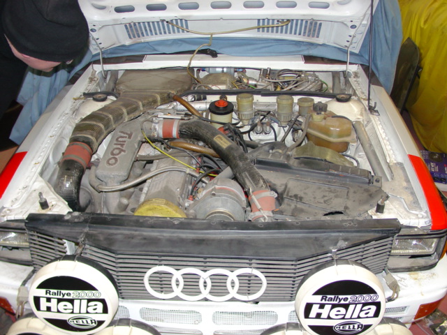
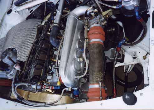
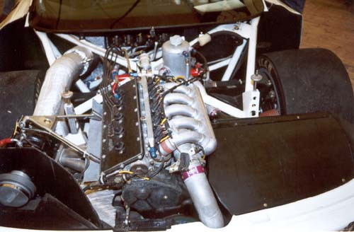
I'll start with the godfather of Audi competition vehicles. The famous 10V motor used in the Group 4 and A2 rally car. This was the staple engine up til the advent of the 20V motor in 1984. Most Audi wins were with this 10V machine. There are some interesting things that can be inferred from this great picture of an A2's engine bay. Here is the Magnesium Intake manifold from a Pierburg equiped car. This is a very early car. The pierburg fuel distributor is placed where the fusebox is on later 94 urquattros. I'm not exactly certain how the air is metered with this setup for the Pierburg CIS. A few notable things to see in this picture. Notice that the tube bracing is aluminum which is typical of not only the braces, but also the replaced front bumper assembly. The firewall is cut down for the airway. Many 20V converted long wheelbase rally cars will still have this cut down firewall which indicates it was a 10V at one time. The unibody is cutaway some on the left and right immediatly behind the headlying and the inner headlight support is removed. The connecting frame of the unibody is removed where the new front grill is. The grill is stiffened by a piece of aluminum tubing which is bolted to the unibody on each end with a two M6 bolts. The timing belt cover is 100% kevlar which is something that is continued on Audi 5 cylinder competition vehicles. The intake hoses are carbon fiber. The turbocharger hoses are original orange silicon which is simliar to what one would fine on diesel trucks of the period. This hosing is still available from Gates Rubber Company. This car is a classic example of a Group 4 car. It has a metal hood. It mostly like has aluminum fenders instead of the kevlar found on the later A2.
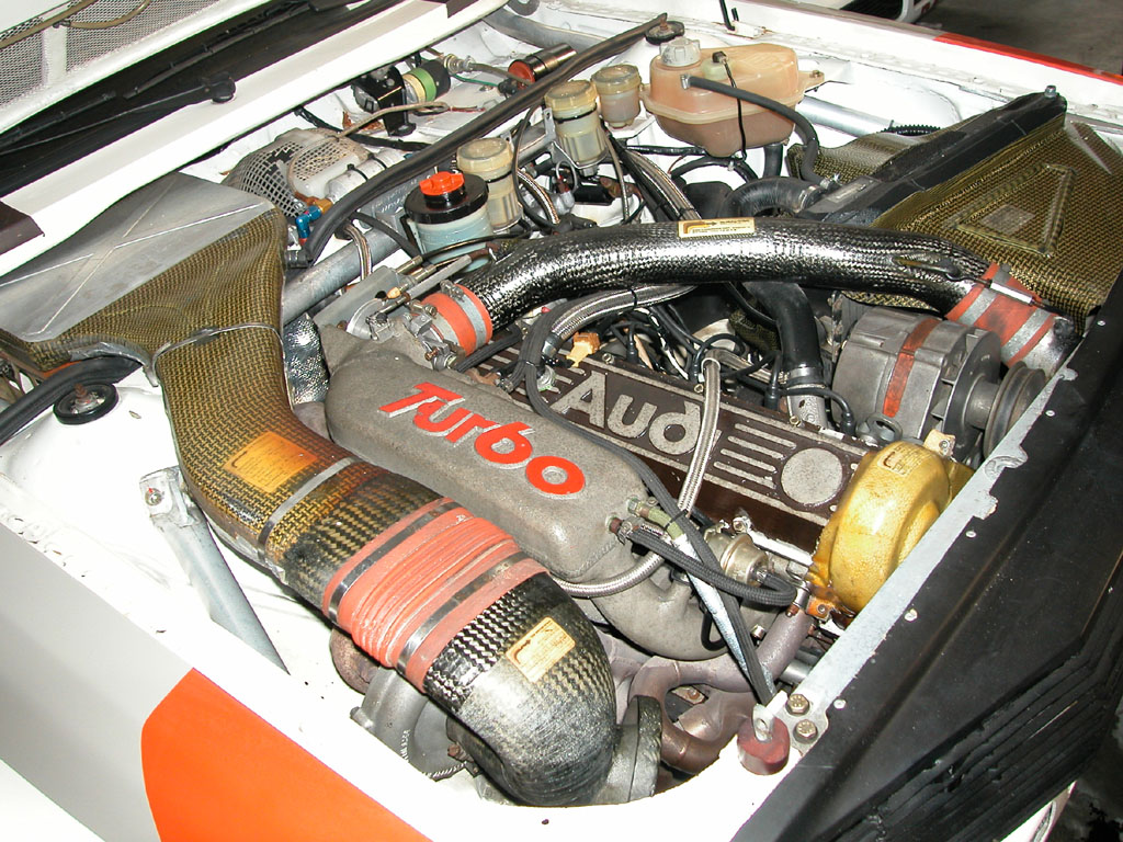
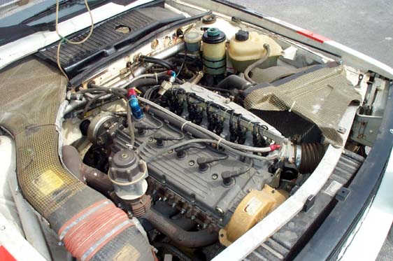
Here is a picture of a later A2 long wheel base quattro. For one, we see a fuel pressure regulator at the end of the fuel rail. The fuel rail more indicative to later 20V cars if fitted on this 10V in an early attempt at Bosch Motronic EFI. There is no CIS components on this setup. This magnesium intake manifold appears to be several casting welded together. This might have been done to facilitate the cost of the casting. The throttle body is a custom weld on job. Overall the compactness of the design leads me to believe this is not a dual plenum design, but merely a hybrid manifold welded together from several different stock parts. Notice the single coil where the old Pierburg assembly was. This car is Motronic but just like other Rally cars it does not have a Mass Air Flow sensor and housing. The system and ECU appear to be tuned using Pressure.
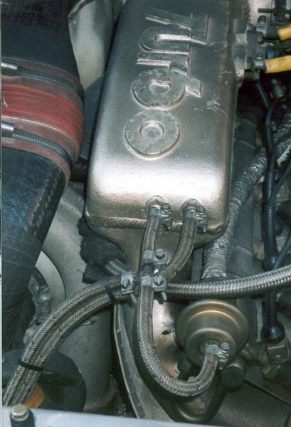
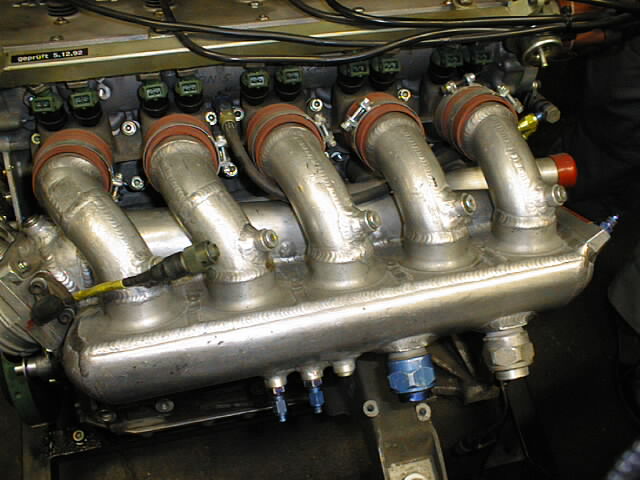
Here is a better shot of the weld seam around the manifold. Note the modern electronic fuel injectors on this 10V car. No CIS.
When Audi introduced the 20V motor. The car was homologated with a
unique special cast intake manifold with a dual plenum. One drawback of
using a single intake plenum is that after the charge air passes through the
throttle body, the pressurized air isn't going to hit the runners going to the
head equally. Runners closer to the front near the throttle body could
very easily get more air than the cylinder furthest away. The Air velocity
could play a factor in this as well. Its a very different concept
when compared against a normally aspirated car where each cylinder's vacuum
draws air into the cylinder so a vacuous single plenum with velocity stacks
makes alot of sense. Also on a normally aspirated car, its very common to
see individual throttle bodies for each cylinder to get maximum airflow with the
least pressure resistance. So how does one actually design an intake
manifold that allows or at least attempts to provide equal airflow to each
cylinder? Well why would one even want to? If modern
electronics allows a different fuel injector pulse to each cylinder, we could
just adjust the fuel flow to compensate for the difference in airflow.
We could do that, but does that actually give us the most efficient use of the
engine's potential? Surely if one cylinder is drawing in 50 cfm of
air and another is drawing in 40 cfm, the ideal thing is to get each cylinder to
take 50 cfm of air. More air means more fuel and that means more power.
So in a perfect engine each cylinder gets an equal amount of air.
Having one cylinder running rich or lean from unequal airflow could lead to
premature engine failure. So simply put. Dual plenum intake
manifolds are turbocharged version of individual throttle bodies.
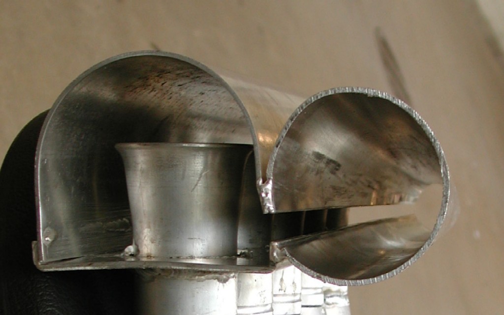
The homologated intake casting for the 20V motor originated with the Sport Quattro street car and the S1 "Shorty" rally car in 1984. This intake manifold is recognized by the forward facing throttle body which works perfectly with a front mounted intercooler. This manifold also have built in mounting points for single or double injectors as well as mounting points for the fuel rail. Its also characterized by its large 2nd plenum which sits over the primary plenum underneath. The primary lower plenum with connects to the throttlebody is gradually tapered like a cone with a continuous single vent slot that allows gas to pass into the 2nd plenum. The 2nd plenum acts as a collector which then feeds the runners to the head. Pressure in the 2nd plenum is equallized since its not effected by gas velocity and inertia or the pressure variation from front to back of the 1st plenum. Since flow equals velocity times area. The reduction in flow which is released through the side slot is equal to the reduction in area of the plenum assuming velocity is constant. So a smooth conical taper with establish equal pressure and air distribution into the 2nd plenum.
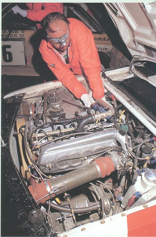
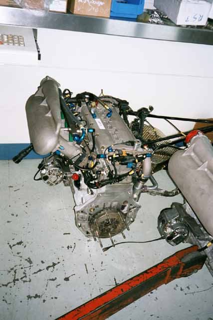
Here is a picture of the early S1 Evo1 of 1984. Note that the car is running dual injectors mounted high on the intake manifold. Pressure readings are taken from the 2nd plenum which is on the top. The air ducting is simlar to a 10V car with a cut down firewall and airbox similar to the A2 Long wheel base. Notice the clever location of the power steering pump being driven off the exhaust cam.
I have this same intake manifold on my car. You can clearly see the flat spots just above my fuel rail which is for dual injectors. You can also see the mounting points for the high fuel rail when using two injectors. I am running single injectors which are closer to the head. Unlike some stock intake manifolds Audi carefully made sure the mounting bolts don't pass through the runners!
JPG.jpg)
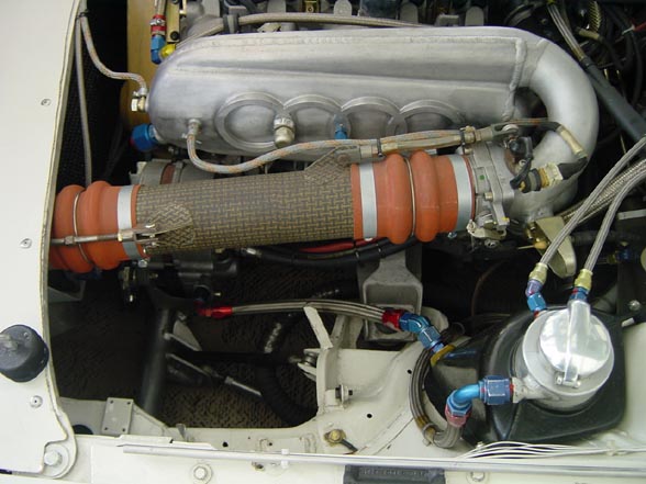
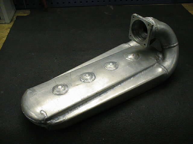
Here is the underside of the early S1 intake manifold. This manifold is commonly called a Lehmann cast intake manifold since its a modification of the Sport quattro sans Water manifold. To be clear, this is not a sport quattro intake manifold. It resembles it from the top, but a Sport Quattro has the water manifold integral to the intake casting. In this picture the conical tapered plenum is to the top and you can see its shape in the casting. The 2nd plenum is equal sized and very much like any other normal single plenum intake.
JPG.jpg)
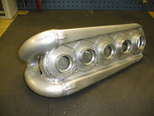
Did Audi use a tapered double plenum on their 10V car? Sure they did. The Trans Am! This photo shows a welded up custom intake manifold for a 10V head with a clear dual plenum with a prominent taper to the 1st plenum. A sinple cone with a continuous slot vent feeding the 2nd plenum.
![]()
Notice the consistency in where the pressure taps are taken. On the 2nd plenum towards the rear away from the throttlebody. This manifold which was fabbed by Lehmann Motoren in Liechtenstein is a great example of custom intake manifold fabrication.
![]()
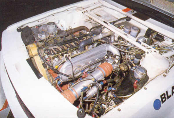
Now the S1 Evo 2. This manifold is a great piece, but obviously mean the radiator had to be moved to the rear. This is a top to bottom design with the conical taper on the topside. Obviously there were some issues with the Cast manifold. Perhaps too restrictive, too small, or perhaps the throttle body location prevented the use of large intercoolers. Either way, this manifold came to be in 1985 and was used on the Pike's Peak cars as well as the Audi Group B S1 Evo 2.
A fabricator in Norway is making this custom intake manifold, but it shows very clearly the dual plenums and the taper and slot of the first plenum. I think the trumpet intakes are excessive in this application. The taper on my cast manifold is more pronounced and reduces to the size of a nickel by the end. This taper appears to still be about quarter size.
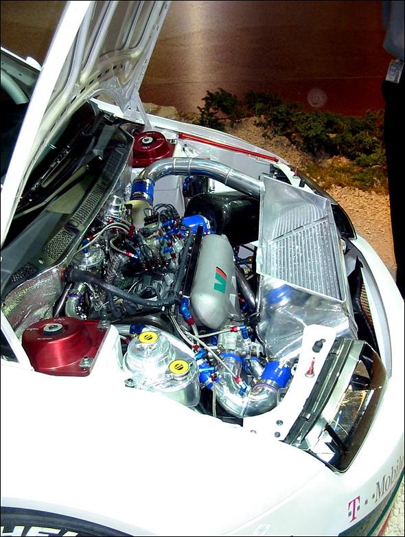
Why change things? A giant radiator of course. Here is the IMSA 90 20V intake. A flipped over dual plenum design. This is a VERY rare car. So its probably the rarest of all the manifolds we've seen here to date. This design is more compact with the tapered plenum tucked under the runners and the 2nd plenum. Its very much an enlarged version of the original Lehmann casting with obviously better flow properties.
Here is a 4 cylinder motor from Lehmann's shop in Liechtenstein. This photo is dated 2000. Note the similarities with the Trans Am manifold
Lehmann does the manifolds for the Skoda rally team. Here is the Skoda WRC
car with a familiar looking intake manifold.
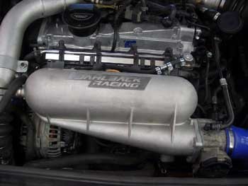
Dahlback and Lehmann collaboration? A great item, I wish something like this was available commercially for the 5 cylinder.
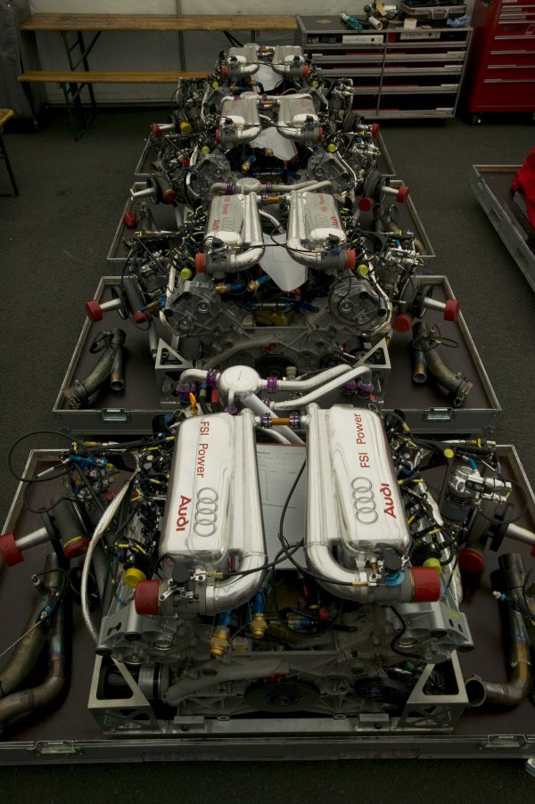
And finally a picture of the engine of the Audi R8 Le Mans car which has won LeMans 5 or 6 times in a row.
This is a twin turbocharge 3.6 liter V8 engine. Please notice the intake manifolds.